Designing the TAG and TPG

The base and tip of the Fin Ray geometry bend towards the applied force.

The caterpillar uses crochets on its legs to grip passively to a substrate, much like a grappling hook passively grips a wall. This means that the caterpillar doesn't need to exert energy to remain on a leaf or a branch.
Design Inspiration
Biologist Lief Kniese of Evologics discovered the Fin Ray Effect while fishing, noticing that fish fins deform such that they bend toward an applied force, which is useful for propelling them through water. The bones in fish fins are arranged in a V shape with connective tissue in-between. Pulling or pushing one side of the frame causes the fin to deform into a crescent-shape. Kniese adapted this into an A-frame structure with crossbeams distributed between the tip and the base. (Hosale and Kievid, 2010, Pfaff et al., 2011)
The Fin Ray Effect is versatile and scalable. Festo has used the phenomena in its DHDG and FinGrippers, which are approximately the size of a human hand and are made from layers of polyamide powder. These grippers are flexible with joints at the connections between the A-frame and the crossbeams, allowing the gripper walls to deform. The effect has also been used on a larger scale as part of an interactive wall, which was 5.3 m (17.4) ft tall, that people could interact with. In this case, the A-frame was composed of a carbon composite and the crossbeams of aluminum tubing. (Hosale and Kievid, 2010) The Fin Ray Effect is easy to design, modify, and manufacture with numerous designs available on Thingiverse, a website where people can share and download 2D and 3D designs for laser cutting or printing.
An animal often overlooked when taking inspiration for robotic manipulators is the caterpillar. The caterpillar is highly successful at climbing and gripping because it must be—falling from a leaf results in the loss of a food source and the potential for starvation. The caterpillar conserves energy by gripping onto a surface passively. This is the opposite of most animals, which require muscle activation in order to continue gripping an object. The caterpillar, and specifically the Manduca sexta, grips a substrate with its crochets, which can be seen above at the end of its prolegs, which act similarly to the way a grappling hook anchors to the side of a wall. When the caterpillar wishes to move, it must activate its muscles to retract the leg and release the crochets before placing the leg in another post. It then relaxes its muscles as the crochets dig into the surface. (Trimmer and Issberner, 2007, Mezoff et al., 2004)
In robotics, passive grip has a number of advantages. A robotic gripper whose natural state is gripping, or closed, does not need continuous power to hold an object. In power-limited environments, such as space or rural areas, the ability to grip passively means that the robot can divert power to other areas such as communication or locomotion. Additionally, in the event the robot loses power, the robot does not drop the object it is holding, making it safer for the people around it as well as preserving the object.
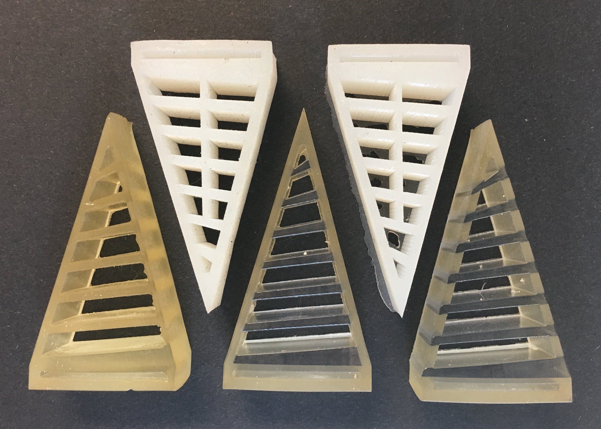
Fin Ray fingers modeled with silicone (top) and 3D printed on a multi-material printer (bottom).

The silicone prototypes were attached to a Baxter robot's electric grippers and used to pick up objects.
Design Testing
I began by creating paper models of the Fin Ray Effect in order to gain a better understanding of how it worked. During this construction, I discovered that by angling the crossbeams with respect to the base, a preferred bending direction could be achieved, meaning it required less force to push one side of the gripper around an object than the other. I then moved to creating molds for casting silicone fingers. I experimented with silicones of varying shore hardness: Ecoflex 30 (Shore A 00-30), Dragon Skin 10 (Shore 10A), Dragon Skin 20 (Shore 20A), and Dragon Skin 30 (Shore 30A). Fingers made from these materials were molded, attached to Baxter’s electric grippers , and tested. The Ecoflex 30 fingers were too soft and the Dragon Skin 30 fingers, while the best of the four, still deformed too much when picking up objects. An additional beam running from the middle of the base towards the tip of the finger was added in an attempt to reduce lateral deformation, but the fingers were still incapable of picking up most objects. It was clear that hard parts needed to be added to the factor, but their addition would complicate the molding process.

Final Designs
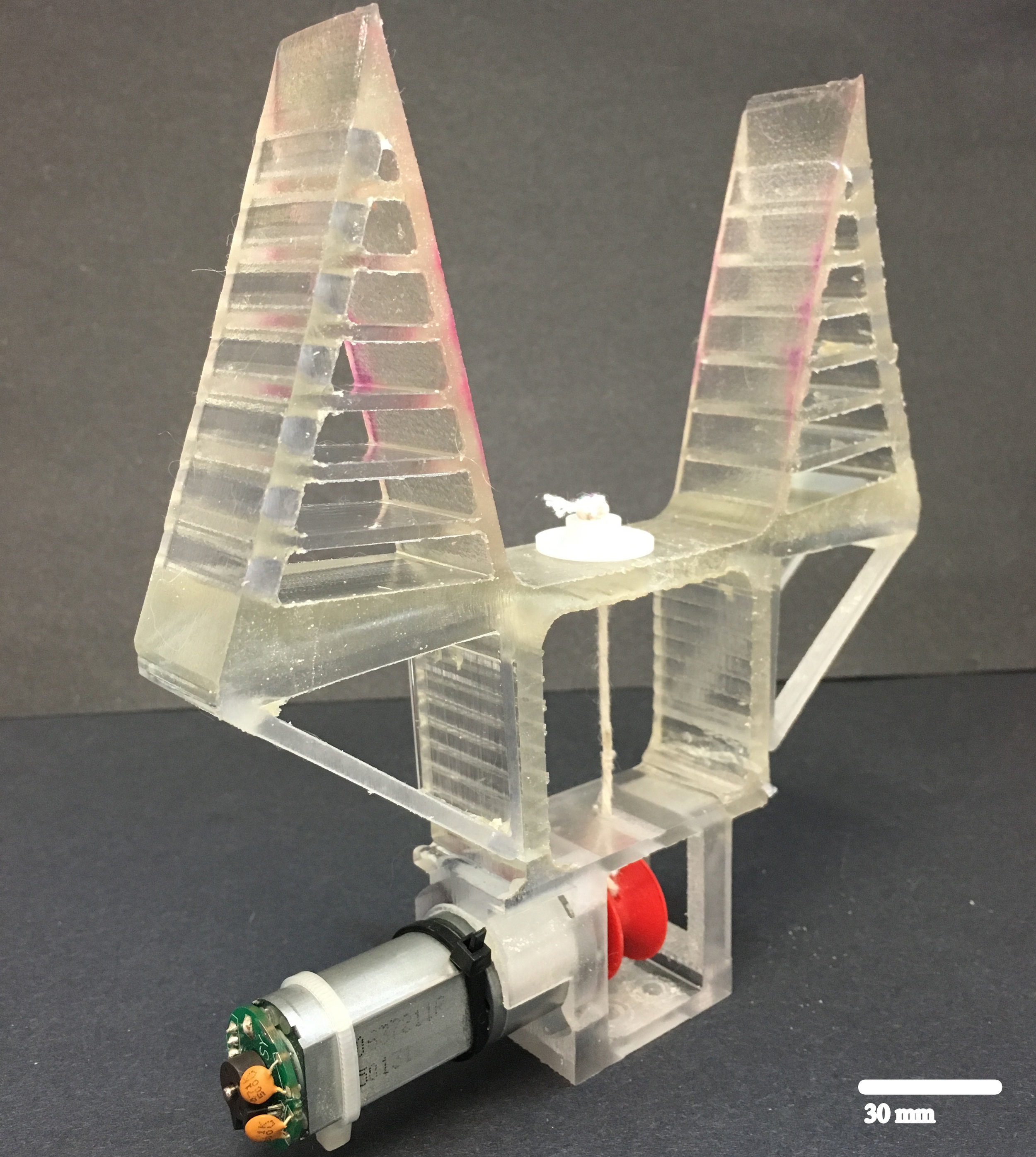
The TAG consists of two Fin Ray Effect inspired fingers with angled cross- beams connected by a soft palm. The fingers are soft with the exception of the crossbeams and hard supports on the exterior side of the exterior side of the fingers. These hard components were included to increase the strength of the finger and decrease the lateral deformation under a load. Two joints with embedded hard trapezoidal prisms connect the palm to the motor holder. A tendon runs from the base of the palm to a pulley attached DC motor, and when the tendon is wound around the pulley, the palm is pulled toward the motor, causing joints bend outwards, press against the hard triangular supports attached to the fingers, and close the fingers around an object. A fingernail was added after several researchers reported that it enabled their soft manipulators to better slide along a surface and to gain a more stable grasp on objects to be picked up.
The TAG is actuated by a motor/tendon sytem. A tendon is attached to the base of the palm and connects to a pulley mounted to a Digilent 12 V DC motor. When the motor is rotated, the tendon pulls the palm toward the motor, collapsing the joints outwards into triangular supports on top of the fingers. The pulling of the palm and pushing against the triangular supports cause the fingers to move inward and around an object. The motor is spun in the opposite direction to release the object and allow the hand to return to its resting state.
The TPG was developed after the TAG with the additional goal of creating a gripper that was passive and inspired by the Manduca sexta. Like the TAG, the TPG is primarily soft with hard material used for the crossbeams, side supports, and motor holder. The fingers of the TPG rest in a closed state and overlap at their tips. Unlike the TAG, the TPG fingers are not completely triangular. At the base of the Fin Ray geometry on the exterior side of each finger, the segment is concave instead of straight. This decreases the torque required for the motor to open the hand and allows for repeatable buckling in that section. The concave segment is also employed as a spring to help the gripper return to its initial state. Another difference from TAG is the crossbeams, which in TPG are surrounded by soft material and do not extend all the way to the finger walls. This was changed in order to minimize the stress concentration at the exterior wall, which caused tearing and failure, and to prevent the hard and soft materials from separating.
The TPG is actuated by a HS-645MG High Torque, Metal Gear Premium Sport Servo (Hitec RCD), capable of 7.7 kg/cm of torque at 4.8 V, was used as the motor, and string was used as the tendon. The motor winds the tendons around a pulley on a servo motor shaft, causing the gripper to open. Spinning the motor back to its neutral state allows the hand to close.