Optimizing the TAG and TPG

-7.5° crossbeam angle
-7.5° crossbeam angle

-7.5° crossbeam angle
Optimizing Cross Beam Angle
While exploring the Fin Ray Effect by constructing paper models of the geometry, I noticed that by angling the crossbeams with respect to the base, I could create a preferred bending direction. To verify and optimize this discovery, I simulated the TAG finger curling around an object in Nastran In-CAD, a finite element analysis (FEA) software. The finger was modeled in silicone and the cylindrical object was modeled in ABS, a rigid plastic. The crossbeam angles were varied between -15° and 15°, and motion around three different cylindrical objects (D = 30, 50, and 70 mm) was simulated. A 1 N force was applied, and the distance the fingertip displaced was recorded.
The optimal crossbeam angle depended on the size of the object the finger was curling around. For 30 mm, the fingertip displaced the furthest for an angle of 2.5°, for 50 mm -7.5°, and for 70 mm -5°. These results suggest that especially for larger objects, a negative crossbeam angle is best.

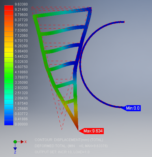
The traditional Fin Ray effect subjected to a 10 N load.

The optimized Fin Ray effect subjected to a 10 N load.
Comparison of Optimization to Traditional
When the fingers were subjected to a 5 N load (Figures 3.1(a) and 3.1(c)), the simulated traditional finger moved 8.14 mm while the simulated TAG finger moved 9.17 mm, approximately 15% further. Similarly, when subjected to a 10 N load, the simulated traditional gripper moved 16.8 mm while the simulated TAG finger moved 19.0 mm approximately 15% more. The larger movement shows that the TAG gripper can move farther toward the object with less force, resulting in a better grip for a smaller actuation.
Discrete force readings of the TAG were recorded and compared to the FEA models for three different applied forces. On average, the normal forces exerted that were measured experimentally were approximately 20% larger than those determined by FEA (0.75 ± 0.13 N compared to 0.62 N). This difference is likely due to the addition of hard crossbeams to the gripper that were not represented in the material model, which was composed of silicone. The inclusion of hard components would enable the gripper to produce larger normal forces than the TAG would have otherwise been able to produce.